There’s a number of moving parts to be considered while configuring logical networking in System Center Virtual Machine Manager 2012 R2 . In this post, I attempt to document my steps in creating and configuring the Logical networks, logical switches, Port profiles, VM networks and Network sites/Logical network definitions that enable the extension of my Windows Server 2012 R2 DHCP based network with multiple Vlans and subnets into the Virtual Machine Manager networking space.
There are a lot more modifications that can be made to suit specific design goals, but I hope to use this post to note the basic sequence of steps and elements that I think need to be in place to help expand on any further infrastructure design and hosting objectives.
My configuration steps are outlined as follows:
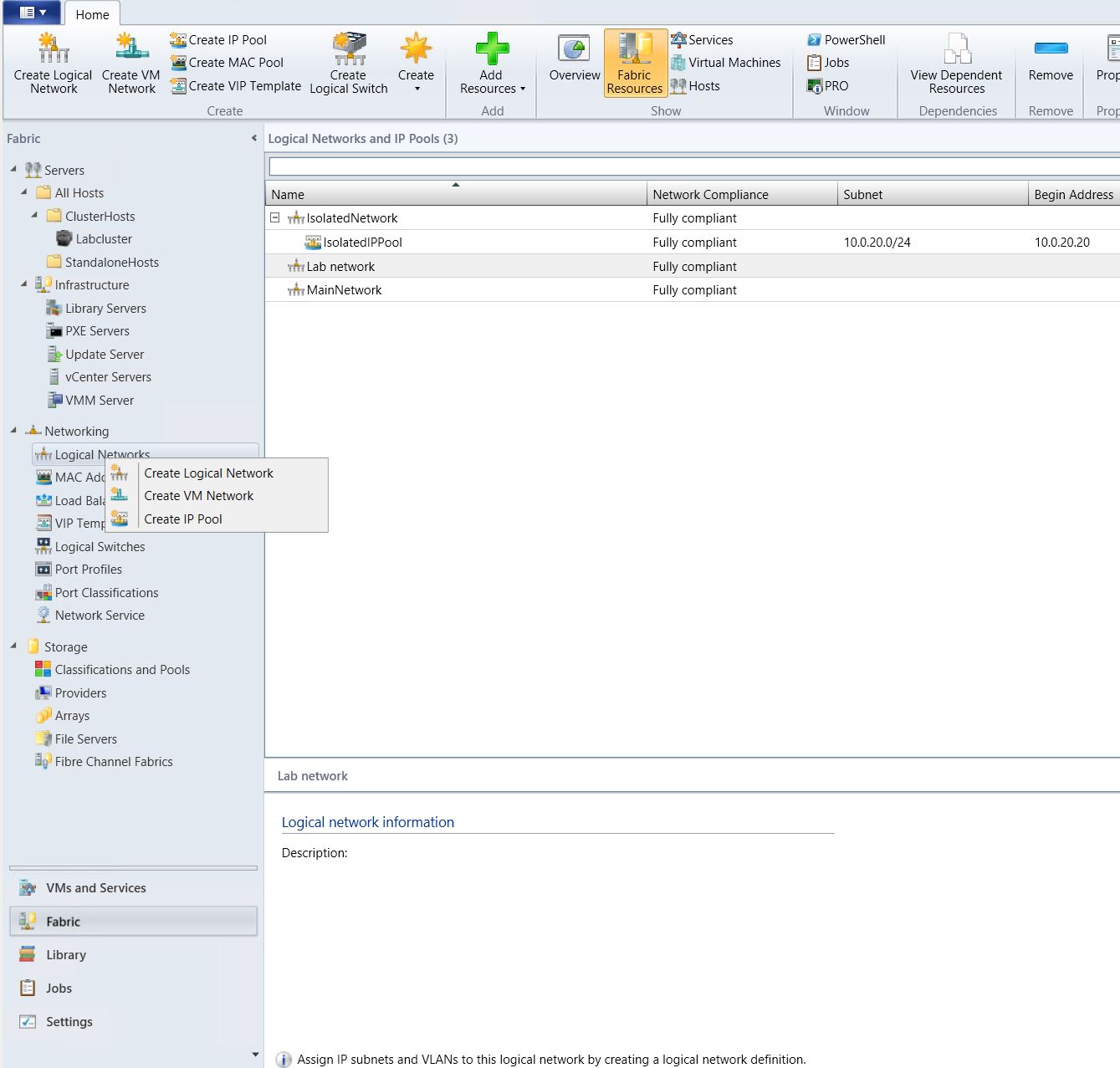
1) Login to the System Center Virtual Machine Manager 2012 R2 Console and navigate to the Fabric workspace.
2) Select and right click on the Logical Network folder and select to “Create Logical Network”.
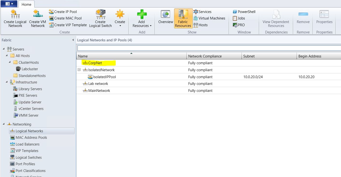
3) On the “Create Logical Network Wizard Name” page, enter a name for the network: CorpNet. Select the “One Connected Network” option and tick the box to “Create a VM network with the same name to allow virtual machines to access this logical network directly”. Click next.

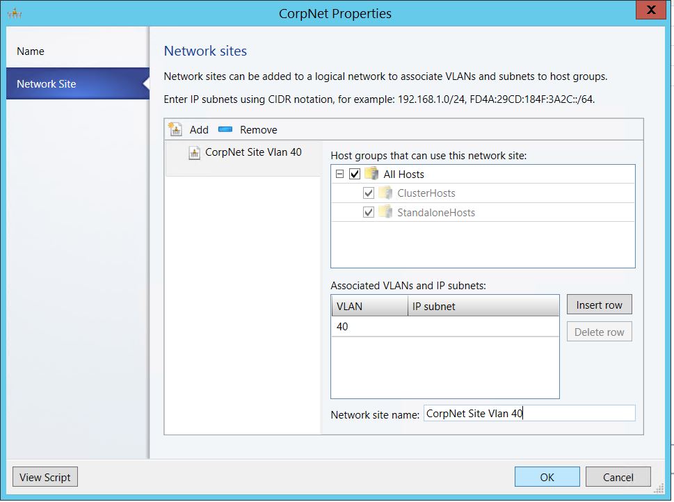
4) On the Network Sites page, click Add to auto create a network site. In the host groups that can use this network site section, check the box to select all host groups. In the associated vlans and ip subnets section, click insert row to add the designated corporate vlan . Since we are extending the corporate subnet, we don’t have to enter the CIDR notation for the corresponding VLAN 40. I renamed the Network Site to “Corp Net Site Vlan 40”. Before clicking the finish button, I prefer to view the PowerShell script for the Logical Network creation process and save the script for future use. Click next to confirm the settings and finish.
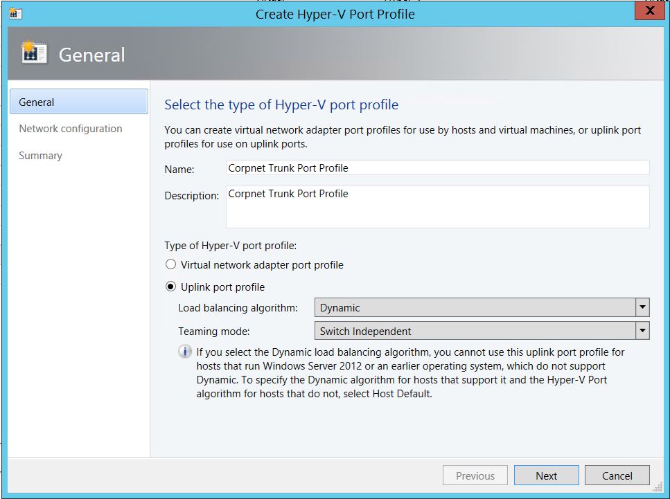
5) The next logical sequence of steps in this process will be to create a Logical switch for this network. But I’ll take a pause to create a Port Profile to be used by the logical switch for the VM host.Uplink Port Profiles define which logical networks can be connected to through these ports. Still in the Fabric workspace, navigate to the Port Profiles folder under Networking. Right click on Port profile and select “Create Hyper-v Port Profile”. On the General page, enter a name for the port profile: “Corpnet Trunk Port Profile”. For the “Type of Hyper-v Port Profile, select Uplink Port Profile. Select Dynamic for Load balancing algorithm and Switch Independent for Teaming mode. Click next.
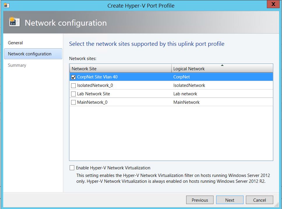
6) In the Network Configuration page, select the network site and associated logical network to be mapped to this Port Profile and click next. On the next page, confirm settings, use the View Script button to view and save the port profile creation PowerShell script for future reference and finish.
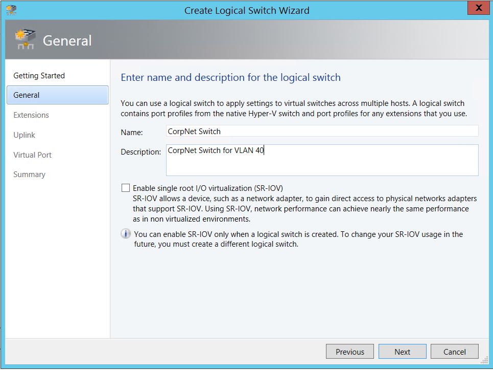
7) Still on the Fabric work space, right click on the Logical Switches folder and select to Create Logical Switch. On the General page, enter a name and description for the Logical switch as “CorpNet Switch”. I have no interest in enabling SR-IOV at this time. Click next.
8) On the Extensions page, select the Microsoft Windows Filtering platform and click next.
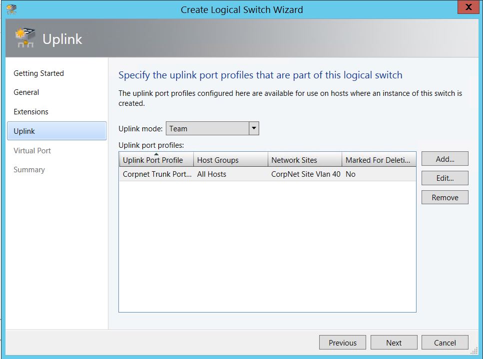
9) On the Uplink page, select Team as the Uplink mode and add the just created CorpNet Trunk Port Profile as the uplink port profile. Click next.
10) On the Virtual Ports page, I selected the Medium Bandwidth label. Confirm the settings, view the PowerShell script and save, then finish.
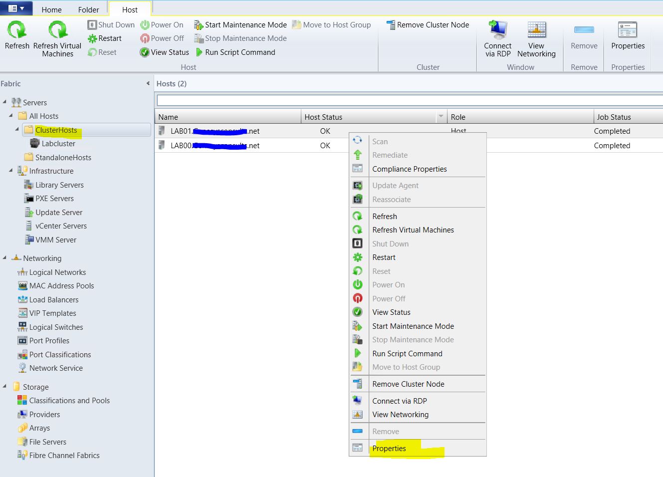
11) In the next step, I’ll associate the new logical switch to both of my cluster nodes to make it highly available.The first host/node is Lab01. Still in the Fabric work space,navigate to the host/cluster group with the designated host with name Lab01 and select the host in the Hosts pane. Right click on the Lab01 host and select Properties.
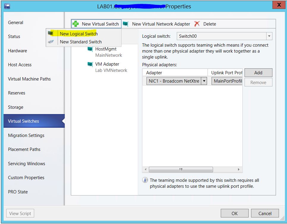
12) Select the Virtual switches tab. Select New Virtual Switch button and select the New Logical Switch option.
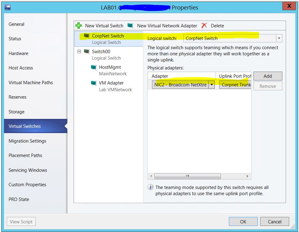
13) Make sure the new CorpNet logical switch is selected. In the host physical Adapter drop down menu, select the physical adapter NIC2 that’s been designated for this logical switch. Click OK.
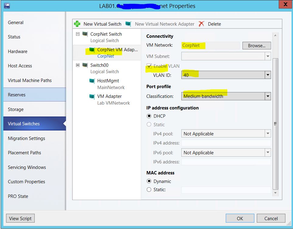
14) Still on the Lab01 host properties page, click on the New Virtual Network Adapter to create a VM adapter off of the CorpNet logical switch. In the VM Network field, browse to select the CorpNet VM Network. Check the Enable Vlan box and select the VLAN ID 40 in the drop down. In the Port Profile classification, select the configured Medium bandwidth label. Click OK. I followed the same steps for the second cluster node/host Lab00.
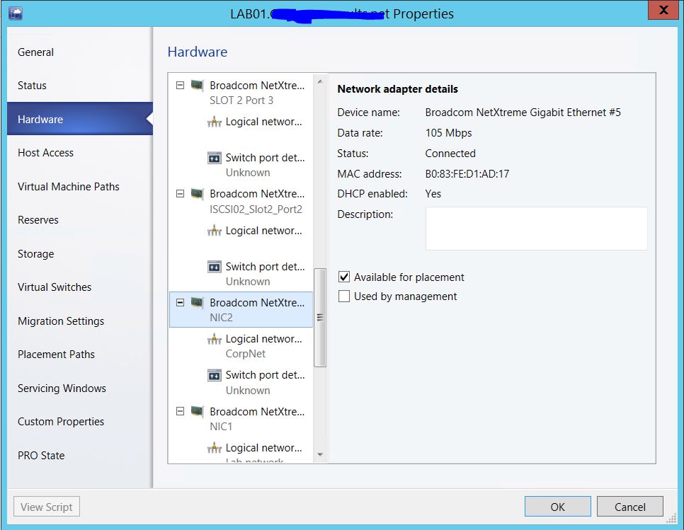
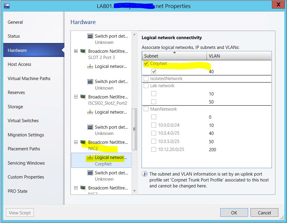
15) Still on the Lab01 host/node Properties page, navigate to the Hardware tab and scroll to the designated Physical Adapter NIC2. Check the “Available for Placement” box to make the logical network configurations available to this adapter and by extension the Virtual Machines on this host/node.
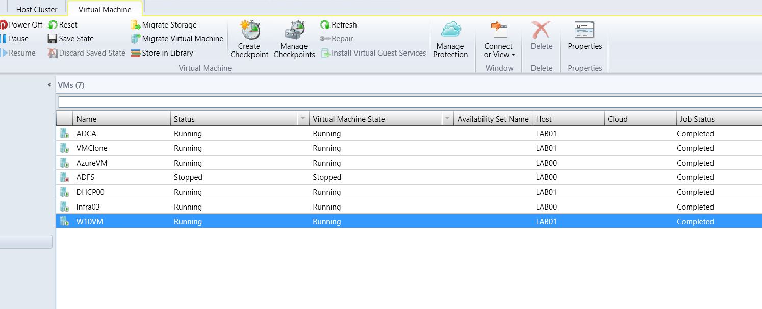
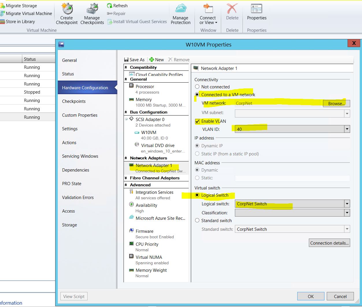
16) In the next step, I will associate a Virtual Machine W10VM on the Lab01 host to the new logical network via the VM Network CorpNet. In the SCVMM 2012R2 console, navigate to the VMs and Services work space. In the VMs pane, select the Virtual Machine W10VM that will be used to test the new network. Right click on the VM and select Properties. In the W10VM properties page, select the Hardware Configuration page. Under the Network Adapters page, select the existing network adapter 1. Under Connectivity, select “Connected to a VM Network”.
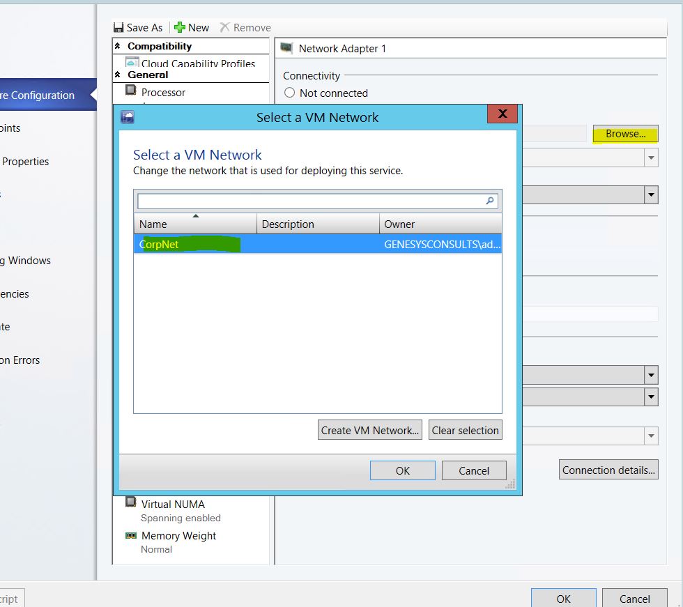
17) For the “VM Network” field, browse to select the CorpNet VM Network on the “Select a VM Network” page , then click OK. Check the Enable VLAN check box and select VLAN ID 40 from the drop down. This VLAN ID was configured as part of the network site configuration. Under the Virtual Switch section, select Logical switch and select the CorpNet Switch from the drop down. View the script and save for future reference. Click OK.
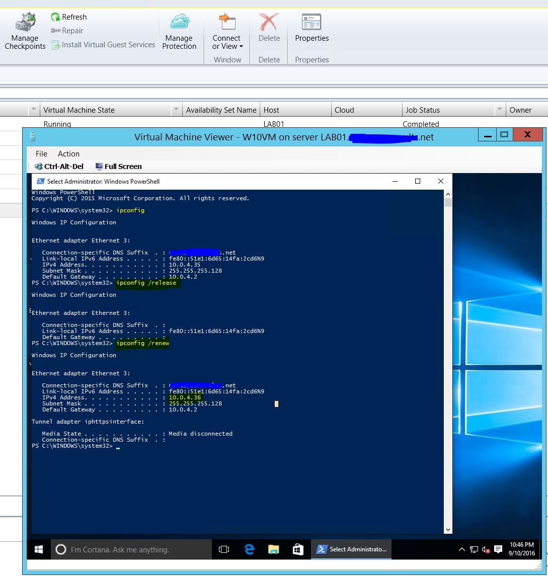
18) To complete the test, start a SCVMM 2012R2 console connection to the W10VM virtual machine and login. Open a PowerShell console and run ipconfig /release and ipconfig /renew to confirm that the VM IP Address is in the VLAN 40 subnet of 10.0.40.0/17 subnet as assigned by the DHCP Server.
As a side note, I will add that the upstream Cisco switch port to the physical network adapter on host Lab01 had already been configured as a Cisco Trunk port. This will allow any VLANs configured in the network site for the Logical network to pass through to the Virtual Machine via the VM Network.
